Flow and Fracture in Viscoelastic Fluids

Josh Gladden, current position: Univ. of Mississippi, Dept. of Physics
Andrew Belmonte, The Pennsylvania State Univ., Dept. of Mathematics

Phys. Review Letter:
Phys. Rev. Lett. 98, 224501 (2007)  [PDF]  [ cover image ]

Movies:
Tearing Dynamics: [MPG]  (15 Mb)
Birefringent Stress Pattern: [MPG]  (2.5 Mb)
Stress in a Fluid
Popular Press:
"Physics News of 2007"
  by APS [ PDF ]

American Institute of Physics News Update
(May 21, 2007)  [ go there ]

Physics Today [PDF]
Volume 60, Issue 7, July 2007

SoftPedia
"How to Cut a Liquid with a Knife" [PDF]

Press Releases from:
Penn State [ go there ]
Univ. of Mississippi [ go there ]


What are viscoelastic fluids?
Viscoelastic materials comprise a wide variety of materials which will snap back after being stressed but lose a rather significant amount of energy along the way.  A consequence of this energy loss is that there is a time lag between when the stress is released and when the material fully snaps back - defining a relaxation time (lambda) in the material.  This relaxation time is an important parameter because it defines a boundary between a solid-like response (like tearing or cracking) and a fluid like response (like flow).  Some typical "everyday" examples of viscoelastic materials would be: toothpaste, gelatine, the earth's mantle, and blood clots.  In the Pritchard Lab in the Math Department at Penn State University, we performed a simple set of experiments in which a rigid cutting tool, typically a cylindrical or square rod, is dragged through a shallow layer of viscoelastic material (1-2 cm deep) with varying speeds and rod diameters.  See the schematic diagram below.

Schematic


Wormlike Micellar Fluids

We chose very concentrated wormlike micellar (WM) fluids as our viscoelastic medium.  WM fluids are essentially a mixture of an organic salt and type of soap or surfactant in water producing long thin tubular like structures in the water which are very weakly bound together and can heal themselves if ripped apart.  WM fluids are transparent for a wide range of concentrations, self-heal when torn apart, and are highly birefringent.  This last quality allows us to visualize stress fields in the fluid by using crossed polarizing filters.  The photo at the top of the page shows the stress field around a square rod (outlined in white) moving through the fluid to the right.   The strong left-right asymmetry in the dipolar field is due to the energy relaxation described below. WM fluids are often studied as model complex fluids which have some similarlities to biological materials.  More information can be found on Prof. Belmonte's website.

flow_cut_tear   Phase Diagram

How the fluid responds
By varying the speed (U) and diameter (d) of the rod moving through the fluid, we observed three distinct responses which are shown in the left image above.  Flow was very smooth fluid movement of the fluid around the approaching cylinder and recombining behind it with no air gaps, but leaving a shallow crease in the surface which lasts on the order of a minute.  The Cut phase occurs when the cylinder speeds up so that a small air gap forms behind the cylinder and the wake walls become textured.  As the wake walls recombine, air bubbles are trapped leaving a trail. The Tear phase occurs when the speed of the cylinder further increases so that extensional stresses in the wake walls become so great the the wall splits generating a crack propagating laterally into the fluid.  These three phases of the fluid response are fully mapped out in the phase diagram shown in the right panel of the figure above.  The solid curves indicate phase boundaries.

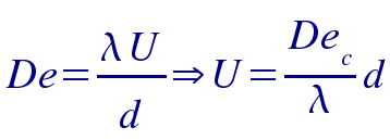
The linear Cut - Flow boundary can be readily explained using an stress relaxation argument, or in the language of fluid dynamics, a critical Deborah (De) number.   De  is a ratio of the relaxation time to the flow time scale  and for  a fluid moving around a cylinder it is
 deborah

We see the linear scaling and our fitted slope and measured relaxation time of 1.1 seconds from rheology experiments gives us a critical Deborah number of 1.  This means the onset of the cutting phase occurs when the fluid tries to flow faster than the relaxation time allows.  It therfore must relieve the energy by small tears on the surface producing the texturing in the walls.

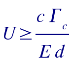
The Tearing boundary scaling of U ~ 1/d is much more difficult to derive.  This is mainly because it involves the initiation and propagation of a crack into a highly viscoelastic material and the theory for this is poorly understood.  However, using a simple critical line stress argument and an estimate for the force exerted on the wake walls by the cylinder, we can derive a scaling law which does seem to agree with our observations:
tear_scaling
where c is the speed of sound, E is Young's modulus, and /Gamma_c is the critical line force or tearing strength for the material.

What else did we see?
We observed a wide variety of interesting dynamics such as a crack that occurs in front of the cylinder which oscillates about the line of motion, very characterstic shark fin like tearing patterns as shown above, and unique birefringent stress patterns which depend on the geometry of the cutting tool.