ELECTRON CHARGE-TO-MASS RATIO
We use a Helmholz coil to bend a beam of electrons into a circular path, The electron's charge-to-mass ratio is proportional to inverse square radius of curvature of the beam.- a profound measurement in days when the electrons's charge and mass were not well understood!
e/m = 2Vacc / B^2r^2 (1)
Vacc is the accelerating voltage, B is
the magnetic field intensity in Tesla, and r is the beam radius
in meters.
Apparatus:
1) We must first obtain the central value of the magnetic field intensity in the Helmholtz coil, figure-1. Using the gaussmeter, a series of measurements were recorded of the of the Helmholtz coil B-field vs current IB , see table -1.
You should enter these values in a spreadsheet and plot I(x-axis) vs B(y-axis). Fit the values to a straight line equation to obtain a parametric equation of B(I) = a + b IB . You will use the equation to find B in the coil.
FIGURE-1: Helmolz Coils
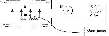
TABLE-1:
.B vs I
| IH (A) | 1 | 2 | 3 | 4 | 5 | 6 | |
| B (gauss) | 2.0 | 3.9 | 5.8 | 7.8 | 9.7 | 11.6 |
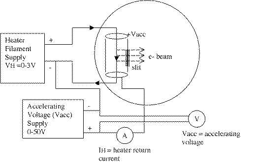
2) The filament supply sends current to the filament wire which runs down the center of the accelerating can inside the e/m tube. The wire will glow as it thermionically emits electrons. The electrons are accelerated to the outer can and some pass through a narrow slit forming the beam. The can's accelerating voltage (+Vacc) must be positive with respect to the filament to attract electrons. Most elecrons do not pass through the slit but return through the circuit. This heater return current IH is a measure of the beam brightness or intensity. If IH is too high the filament could burn out (like a fuse!). IH should remain below 3ma for safe operation.
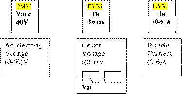
Vacc < = (30-50) V 40V
nominal
VH = ( 2.5-3.0 )V
IH
= (2.5-3.0)ma
IB = (0-6) A
FIGURE-2:
Helhmolz Coils and power supplies.
Startup Sequence
1) First set the accelerating voltage Vacc = 30V. This will act
to remove electrons from the heater wire as we turn up the heater
current.
2) Set the Helmholz coil current IB to about 1A to initially
apply a small magnetic field.
3) Slowly increase the heater voltage VH to 2V as read from the
power supply dial. You should observe the heater wire begin to
glow red in the e/m tube (slit). The heater current IH should
increase to about 1.0 ma. Stop and let the circuit burn-in for
a while. You may observe the heater return current IH drop.
Increase the heater voltage VH a bit to compensate, keeping the heater current
IH
~ 1.0ma.
4) Wait for tha circuits to become stable.
5) Slowly increase the heater voltage VH to 3V and the heater
return current IH will rise to ~(2-3)ma. You should observe the
electron beam emerging from the slit and bending in the B-field.
The electrons are exciting Hg atoms in the tube, who emit a soft
purple glow. Change the magnetic field current and note the change
in circular path.
6) During measurements keep the heater return current IH at about 2.5 or 3.0 ma. This will allow you to easily see the electron beam.
Measurement and Error
1) With the accelerating voltage Vacc set to 40V (KE e= 40eV!)
bend the electrons to each post and record the magnetic field
current IB. The electrons at the outer edge of the beam
are the most energetic. These electrons have suffered fewer Hg
gas collisions in the tube. Adjust the beam so the outer electrons
just hit the posts for best accuracy of measurement. You can wiggle
IB
up and down a bit to define a hi-lo range for defining your error
err(IB)
on IB.
Take two readings at each post, in-to-out and then out-to-in.
TABLE-2: Data Record and sample data for posts 1,2,3
| post | 1 | 2 | 3 | 4 | 5 | 5 | 4 | 3 | 2 | 1 |
| IB | 3.00 | 2.97 | 30.1 | |||||||
| B(IB) | 5.94e-4 | 4.99e-4 | 4.38e-4 | |||||||
| Vacc(V) | 30.1 | 29.7 | 30.1 | |||||||
| R(m) | 0.033 | 0 .038 | 0 .045 | |||||||
| e/m C/kg | 1.57e11 | 1.65e11 | 1.55e11 |
Shutdown Sequence
1) First slowly turn down the heater voltage VH to zero and then OFF
MOST
IMPORTANT!
2) Next the magnetic field current, IH to zero and then OFF.
3) Finally the accelerating voltage Vacc to zero and then OFF.
Analysis
1) Calculate the e/m ration for
each reading in Table-2. You will need to find B(IB).
2) Average the e/m for each post from
the two readings and take half the difference for the error.
Tabulate your answers like below.
TABLE-3 e/m results
| post | e/m +-err(e/m) |
| 1 | 1.57e11 |
| 2 | 1.65e11 |
| 3 | 1.55e11 |
| 4 | |
| 5 |
| e/m | err(stat) | err(syst) |
| 1.59 e11 | 0.05 e11 | (1.76-1.59)e11=0.17e11 |
3) Plot the e/m ratio (with error bars)
vs post number. If this is flat then you may average all the e.m
values in table-3 for your
final answer with standard deviation as error. If the e/m values
are not consistent at each post use the value at the inner post
and discuss the problem. The variation over the 5 posts can be
used to estimate a systematic error.
4) How accurate is your measurement? or How well does your measurement agree with the accepted value (% difference)?
5) Be sure to discuss statistical and systematic errors in your report.